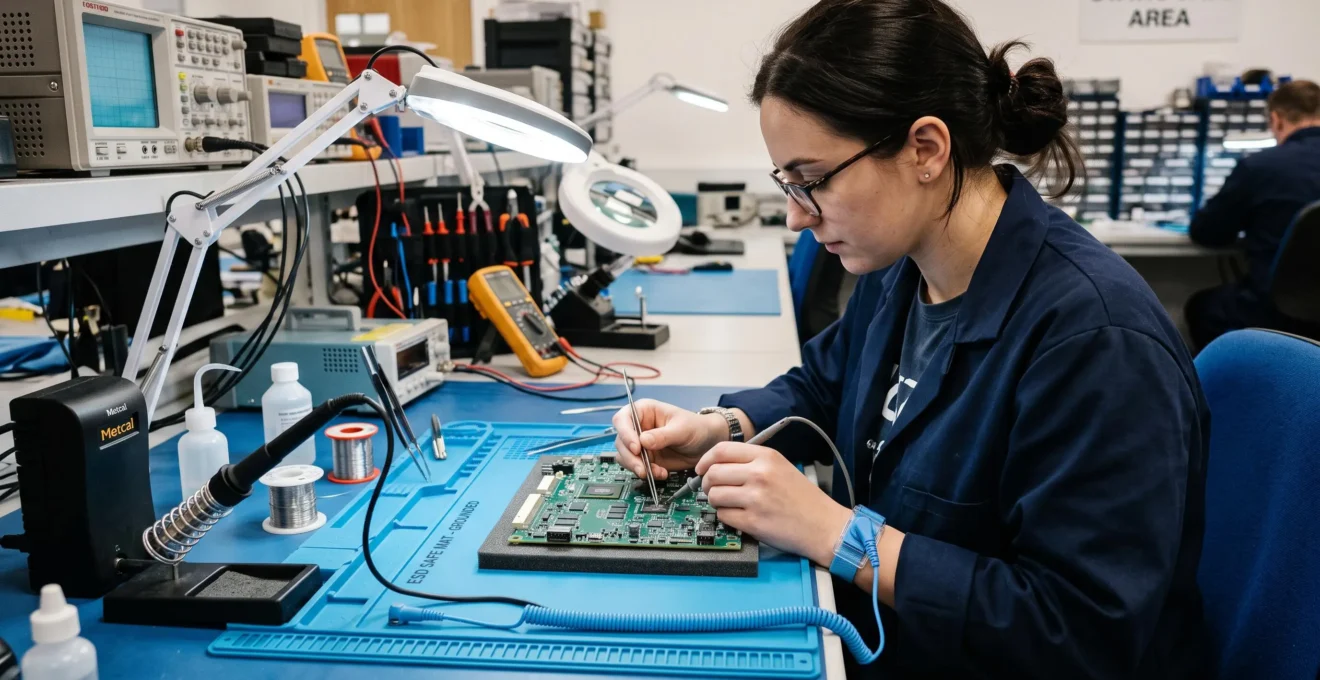
A technician wears an anti-static wrist strap throughout an eight-hour shift, diligently connecting it each morning before handling surface-mount components. The equipment shows continuity when tested. Yet weeks later, £15,000 worth of integrated circuits fail prematurely in the field. Investigation reveals the workbench itself lacked a verified earth connection—the wrist strap was grounded to an isolated metal surface, creating the appearance of protection whilst providing none. This scenario illustrates a critical reality: wearing grounding equipment does not guarantee effective electrostatic discharge (ESD) protection. True safety requires understanding the complete charge dissipation pathway, from operator through equipment to verified earth, alongside routine verification that this pathway remains intact.
Industry experts from the Electrostatic Discharge Association (ESDA) estimate that product losses due to ESD events account for a significant portion of total electronics failures.. For UK electronics manufacturing facilities handling CMOS integrated circuits, motherboards, and specialist semiconductors, the financial impact can be severe—individual component replacement costs range from £5 for basic devices to £500 or more for specialist ICs. Yet the insidious nature of latent ESD damage means many failures go undetected until field deployment, when repair costs multiply exponentially.
Establishing a verified earth connection requires a systematic approach to workplace configuration. To ensure that technicians remain at the same electrical potential as the sensitive components they handle, it is necessary to integrate professional-grade personal grounding equipment into the assembly workflow. These specialized tools provide the essential pathway for continuous charge dissipation, preventing the silent accumulation of voltage that leads to latent component failure and maintaining a defensible protection standard.
This guide explains the principles underlying effective grounding, provides decision frameworks for selecting appropriate equipment based on workspace context, details verification procedures technicians can perform without specialist testers, and identifies common implementation errors that create false security. The approach bridges theoretical understanding with actionable procedures, enabling confident implementation and team training whilst addressing cost justification concerns through risk-based equipment selection.
This guidance addresses ESD grounding for component protection. All earthing procedures must comply with the Electricity at Work Regulations 1989 and relevant HSE guidance. When uncertainty exists regarding electrical safety, consult a qualified electrical engineer before implementation.
- Why proper grounding matters when handling ESD-sensitive devices
- How does personal grounding actually prevent electrostatic damage?
- Essential personal grounding equipment for electronics work
- What grounding method should you choose for your workspace?
- Step-by-step procedure for effective ESD grounding
- How do you maintain and verify grounding equipment reliability?
- Common grounding mistakes that compromise component safety
Why proper grounding matters when handling ESD-sensitive devices
Human bodies routinely generate electrostatic charges ranging from 2,000 to 4,000 volts through ordinary activities—walking across standard flooring, rising from a chair, or simply moving within a workspace. These voltage levels remain completely imperceptible to the operator, producing no sensation whatsoever. Yet CMOS integrated circuits, the core components in motherboards and microprocessors, can suffer catastrophic damage from exposures as low as 100 volts. This severity gap between human charge generation and component vulnerability creates a persistent hazard invisible to unprotected workers.
8–33%
Industry estimates of electronics product failures attributable to electrostatic discharge events, according to ESDA data cited in patent documentation
The damage manifests in two distinct forms, each presenting different detection challenges. Catastrophic failure produces immediate, visible destruction—a component that simply will not function following an ESD event, enabling detection during assembly or initial testing. Far more insidious is latent damage, where the electrostatic event degrades component performance without causing immediate failure. These compromised devices pass initial quality checks, only to fail prematurely weeks or months later during field deployment. Manufacturing facilities often attribute such failures to random defects rather than recognising the ESD events that occurred during assembly, making actual loss rates difficult to quantify precisely.
Not all electronic components require the same level of protection. Understanding which devices demand grounding protocols prevents both costly under-protection and wasteful over-application of controls. ESD-sensitive components requiring mandatory grounding include:
- Integrated circuits, particularly CMOS technology devices (microprocessors, memory chips, logic controllers)
- Surface-mount devices (SMDs) due to their reduced physical size and correspondingly lower voltage tolerance
- Printed circuit boards (PCBs) populated with sensitive components
- Specialist semiconductors for aerospace, medical, or automotive applications with especially stringent reliability requirements
By contrast, traditional through-hole resistors, basic capacitors, and mechanical connectors typically demonstrate sufficient robustness to withstand typical human body voltage levels without protection. Component datasheets specify ESD sensitivity classifications—typically expressed as Human Body Model (HBM) voltage thresholds—enabling risk-based assessment of protection requirements.
Within the United Kingdom, regulatory drivers increasingly complement economic motivations. The Health and Safety Executive (HSE) references ESD control within broader electrical safety duties under the Electricity at Work Regulations 1989, particularly where component damage creates secondary risks such as malfunction in safety-critical systems. BS EN 61340-5-1:2016 serves as the governing standard, establishing technical requirements for ESD-protected areas within UK and European manufacturing contexts. Compliance demonstrates due diligence, whilst failures resulting in product recalls or safety incidents carry both financial and reputational consequences.
Consider the real incident prompting this guidance: a mid-sized electronics facility near Manchester suffered £15,000 in component losses from a single batch of motherboards experiencing premature field failures. Investigation traced the root cause to inadequate grounding during assembly—operators wore wrist straps creating the appearance of protection, yet the workbench grounding infrastructure lacked verified earth connection. The equipment provided false security, a scenario more dangerous than acknowledged gaps because supervision assumed protection existed. This pattern—equipment possession mistaken for effective implementation—represents the most common failure mode in ESD control programmes.
How does personal grounding actually prevent electrostatic damage?
Personal grounding functions by creating an intentional low-resistance pathway to earth, allowing accumulated electrostatic charge to dissipate continuously rather than discharge suddenly through a sensitive component. When an operator connects to verified earth through proper grounding equipment, any charge accumulating on their body flows harmlessly away at a controlled rate, maintaining the operator at earth potential. Without this pathway, charge builds until the operator touches a component, at which point the accumulated voltage discharges through the device in microseconds—fast enough to damage semiconductor junctions whilst remaining imperceptible to human sensation.
This mechanism relies on the principle of path of least resistance. Electrical charge seeks the easiest route to earth potential. A properly grounded operator presents a low-resistance pathway (typically one megaohm through the wrist strap system), far easier than the pathway through a sensitive component to earth. Charge therefore flows continuously through the grounding equipment rather than accumulating to dangerous levels. The process occurs constantly, silently, and invisibly—effective grounding prevents charge accumulation before it reaches hazardous thresholds.
Grounding versus antistatic: complementary protection strategies
Grounding (earthing) creates a pathway to dissipate accumulated charge, maintaining operator and equipment at earth potential. Antistatic materials prevent charge generation through conductive or dissipative surfaces that inhibit triboelectric charging from friction. Both strategies work together: antistatic matting prevents charge generation from contact with work surfaces, whilst grounding dissipates any charge the operator carries from movement elsewhere. One does not replace the other—comprehensive protection requires both elements functioning correctly.
A critical component in proper wrist strap design is the current-limiting resistor, typically rated at one megaohm (1 MΩ). This resistor serves dual functions that might initially appear contradictory. First, it allows rapid dissipation of electrostatic charge—one megaohm provides sufficiently low resistance for ESD purposes, draining typical body voltages in milliseconds. Second, and equally important, it provides electrical safety protection should the operator accidentally contact mains voltage. The resistor limits current flow to safe levels (240V ÷ 1,000,000Ω = 0.24 milliamps), well below the threshold for electrical shock hazard. Equipment lacking this resistor—such as improvised grounding using direct wire connections—creates serious electrical safety risks whilst violating BS EN 61340 specifications.
The concept of equipotential bonding extends beyond individual operator grounding to encompass the entire workspace. When operator, workbench, tools, and components all connect to a common earth point, they exist at the same electrical potential. With no voltage difference between elements, no discharge can occur—charge has nowhere to flow. This system-level thinking explains why merely grounding the operator proves insufficient: if the work surface remains unbonded, charge can still flow from operator through component to isolated workbench, damaging the component in transit. Effective protection requires verifying that all conductive elements within the workspace connect to a common bonding point with confirmed earth connection.
BS EN 61340-5-1:2016 specifies acceptable resistance ranges for compliant wrist strap systems: between 750 kilohms and 35 megohms measured from operator skin through strap and cord to the earth connection point. This range balances rapid charge dissipation (lower resistance = faster drainage) against electrical safety protection (higher resistance = greater current limitation). Values below 750 kΩ suggest damaged equipment with inadequate current limiting, creating shock hazards. Values above 35 MΩ indicate poor connections, degraded materials, or broken conductors—equipment that appears functional but provides insufficient charge dissipation to protect components reliably.
Essential personal grounding equipment for electronics work
Selecting appropriate personal grounding equipment requires matching device capabilities to workspace requirements, operational mobility needs, and component sensitivity levels, operational mobility needs, and component sensitivity levels. The primary equipment categories each address different operational contexts, with selection driven by practical workflow considerations rather than simple preference.
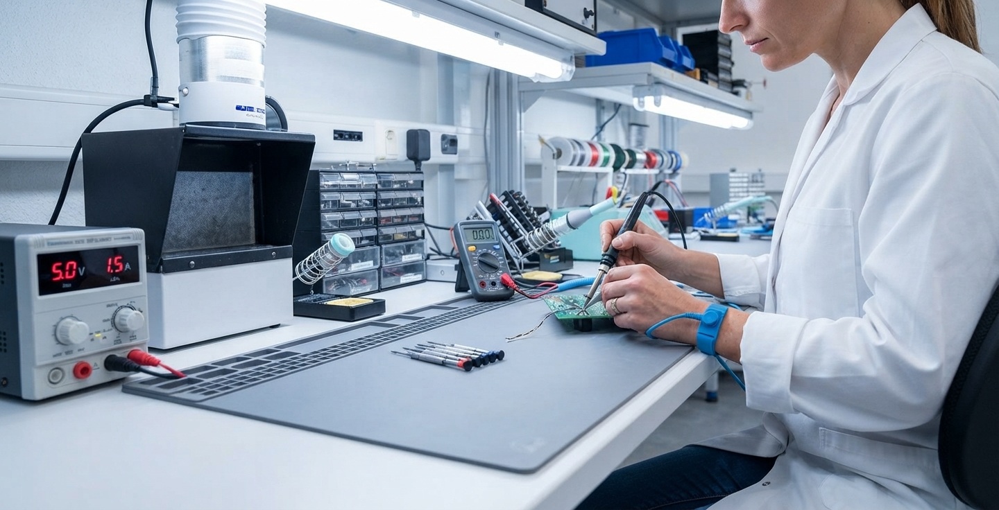
Wrist straps represent the most common grounding solution for stationary electronics work—repair benches, inspection stations, or assembly positions where operators remain largely in one location. A compliant wrist strap system consists of three elements: a conductive band worn snugly against bare skin (typically on the wrist or ankle), a coiled cord containing the current-limiting resistor, and a connection point to verified earth. The band must maintain skin contact without gaps—fabric or elastic sections alone cannot conduct charge. The coiled cord provides operator mobility within a limited radius whilst maintaining continuous earth connection. BS EN 61340-5-1 specifies the complete system resistance of 750 kΩ to 35 MΩ, meaning all three components must function correctly to achieve compliant protection.
Heel grounders provide the primary alternative for mobile operations where a wrist strap cord would impede movement or create trip hazards. These devices consist of conductive straps worn over standard footwear, with conductive elements contacting the floor with each step. Heel grounders require conductive or dissipative flooring to function—they create a pathway from operator through footwear to floor to earth, meaning the floor itself must provide the earth connection. This solution suits cleanroom environments, assembly lines, or warehouse operations where operators move frequently between workstations. The limitation: effectiveness depends entirely on maintaining floor contact and verified floor-to-earth bonding, making them unsuitable for standard insulative flooring common in general-purpose workshops.
ESD footwear offers permanent conductive capability integrated into the shoe construction itself, eliminating the need for heel grounder straps. Conductive or dissipative shoes suit dedicated ESD-protected areas where operators spend entire shifts, justifying the higher equipment cost through convenience and durability. The distinction between footwear and heel grounders comes down to operational context: operators working exclusively in ESD areas benefit from permanent footwear, whilst those moving between protected and unprotected zones (entering cleanrooms from offices, for example) find heel grounders more practical since they can be donned only when entering controlled areas.
Decision factors for equipment selection:
- Work mobility: Stationary positions favour wrist straps; mobile operations require heel grounders or footwear
- Component sensitivity: High-sensitivity devices (HBM <100V) justify comprehensive systems; moderate sensitivity allows scaled approaches
- Existing infrastructure: Heel grounders and footwear require conductive flooring already installed; wrist straps need only common bonding points
- Operational context: Dedicated ESD areas suit permanent footwear; mixed environments suit heel grounders
- Budget considerations: Basic wrist strap systems start around £15-30; heel grounder sets £25-50; ESD footwear £60-150
For high-sensitivity environments—aerospace component assembly, medical device manufacturing, or situations involving extremely voltage-sensitive semiconductors—conductive or dissipative garments extend protection beyond extremities. ESD smocks, lab coats, or full coveralls manufactured from conductive-fibre fabrics prevent the operator’s clothing itself from generating or accumulating charge. These represent advanced protection for specialized contexts where even the triboelectric charging from standard synthetic clothing presents unacceptable risk, supplementing rather than replacing wrist strap or footwear grounding.
What grounding method should you choose for your workspace?
Equipment selection begins with assessing operational mobility requirements, the single most decisive factor determining practical options. Operators who remain at fixed positions—PCB repair technicians at benches, quality inspectors at testing stations, hand-assembly workers at dedicated workstations—can use wrist strap systems efficiently. The coiled cord provides sufficient movement radius for typical bench work whilst maintaining continuous earth connection. This configuration offers the most cost-effective protection for stationary operations, requiring only verified earth points and common bonding infrastructure.
Mobile operations demand different solutions. Assembly line workers moving between stations, cleanroom technicians traversing large areas, or warehouse staff handling components at varying locations cannot remain tethered to fixed earth points. For these contexts, heel grounders or ESD footwear provide continuous grounding during movement. The critical prerequisite: conductive or dissipative flooring covering all areas where components are handled. Standard vinyl, carpet, or sealed concrete provides inadequate conductivity—heel grounders on insulative floors create the same false security as wrist straps connected to unbonded workbenches. Facilities considering mobile grounding solutions must first verify floor conductivity or factor flooring installation into project costs, often representing the largest single investment in comprehensive ESD programmes.
Component sensitivity classification provides the secondary decision layer, determining how comprehensive the grounding system must be. The Human Body Model (HBM) classification system rates component ESD sensitivity:
- Class 0: <100V HBM (extremely sensitive—aerospace processors, RF components)
- Class 1A: 100-250V HBM (very sensitive—CMOS logic, high-density memory)
- Class 1B: 250-500V HBM (sensitive—standard integrated circuits)
- Class 2: 500-1000V HBM (moderately sensitive—some power devices)
- Class 3: >1000V HBM (relatively robust—many passive components)
Facilities handling primarily Class 1B or lower sensitivity components can implement basic protection—verified wrist strap systems for stationary work, or heel grounders with confirmed conductive flooring for mobile operations. Class 0 and 1A components justify comprehensive measures: dual grounding methods (both wrist strap and footwear), ESD garments, ionization equipment to neutralize airborne charge, and stringent verification protocols. The investment scales with risk: a workshop repairing consumer electronics boards (Class 1B/2) faces different protection requirements than a facility assembling satellite components (Class 0/1A).
Workspace configuration constraints impose practical limitations on equipment options. Existing infrastructure determines implementation complexity and cost. Key assessment questions include:
- Do workbenches currently include common bonding points and verified earth connections, or does grounding infrastructure require installation from scratch?
- What flooring exists throughout component handling areas—conductive, dissipative, or standard insulative materials?
- Can workspace layouts accommodate wrist strap cords without creating trip hazards or workflow disruption?
- Are electrical safety requirements already documented under regulations for electrical health and safety, providing foundation for ESD-specific additions?
Budget and return-on-investment analysis addresses management concerns about equipment costs. A basic compliant wrist strap system (band, cord, and common bonding point installation) costs approximately £50-150 per workstation including installation. Heel grounder sets add £25-50 per operator. Conductive flooring represents the substantial investment—£40-100 per square metre for dissipative tile or mat systems, or £80-200+ per square metre for installed conductive flooring in cleanroom specifications. Against these costs, consider single-incident component losses: the £15,000 damage from one unprotected batch typically exceeds the cost of equipping an entire small workshop. The business case strengthens when including warranty costs, customer confidence impacts, and regulatory compliance benefits.
Step-by-step procedure for effective ESD grounding
Correct implementation begins with workspace infrastructure, not personal equipment. The grounding pathway must extend from operator through equipment to verified earth connection. Installing this pathway in reverse order—earth verification first, then equipment connection, finally operator attachment—prevents the dangerous scenario of wearing grounding equipment connected to unbonded surfaces.
-
Verify common bonding point earth connection
Locate the common bonding point (CBP) serving the workspace—typically a grounding bus bar, stud, or socket connected to building earth. Verify this connection using a qualified electrician’s earth continuity tester or by confirming documented earth pathway per Electricity at Work Regulations 1989. The CBP must connect to the general mass of earth through conductors of adequate capacity. Never assume a metal surface is earthed without verification—painted surfaces, anodized aluminium, and isolated metal furniture frequently lack earth connection despite conductive appearance.
-
Connect workspace equipment to common bonding point
Attach the ESD mat ground cord to the CBP using secure, permanent connections (snap fasteners, ring terminals, or purpose-designed grounding plugs). Connect any conductive tool holders, parts bins, or equipment chassis requiring bonding. Each connection point should demonstrate resistance to earth below 1 megohm when measured, confirming adequate conductivity throughout the bonding system. Avoid daisy-chaining multiple items through single connection points, as this creates serial resistance potentially exceeding specification limits.
-
Attach wrist strap band to bare skin
Position the conductive wrist strap band snugly against bare skin on the inside of the wrist or ankle. The metal contact plate must touch skin directly—placement over clothing, sleeves, or fabric watch straps prevents charge conduction. Adjust tension to maintain contact without restricting circulation; bands that slip or rotate during work interrupt the grounding pathway. Some operators prefer ankle placement to avoid interference with hand tool use.
-
Connect strap cord to verified grounding point
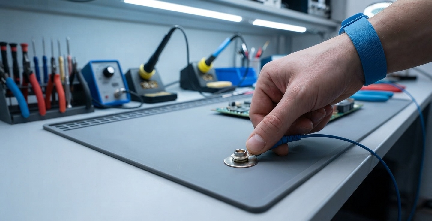
Attach the wrist strap coiled cord to the workstation grounding socket or directly to the CBP. Ensure the connection is secure and metal-to-metal—corroded or loosely fitted plugs create intermittent contact. The cord should allow comfortable working radius movement without excessive tension that might dislodge connections.
-
Perform continuity verification before handling components
Test the complete grounding pathway using a dedicated wrist strap tester or multimeter set to resistance measurement. Touch one probe to the wrist strap band’s metal contact while the other probe contacts the earth point. Acceptable reading: 750 kΩ to 35 MΩ total system resistance. Readings below 750 kΩ indicate potentially dangerous short circuits (damaged resistor); readings above 35 MΩ or infinite resistance indicate open circuits (broken wire, poor connection, or degraded band). Only proceed with component handling after confirming proper resistance range.
For heel grounder and footwear grounding, the procedure adapts to floor-based pathways. Verify conductive flooring connects to building earth through documented bonding infrastructure. Confirm floor surface resistance falls within specified ranges (typically 1 × 10⁴ to 1 × 10⁹ ohms for dissipative flooring per BS EN 61340-5-1). Attach heel grounders to footwear with conductive elements contacting the floor, or don verified ESD footwear. Test operator-to-ground resistance using specialized flooring test kits that measure the complete pathway from operator through footwear and floor to earth.
The operational sequence maintains protection throughout handling. Connect grounding equipment before approaching ESD-sensitive components—ideally as the first action upon arriving at the workstation. Maintain continuous connection throughout the entire work period; disconnecting for “quick tasks” creates exposure windows where dangerous charge can accumulate. Disconnect only after components are secured in protective packaging or returned to ESD-safe storage. This discipline—grounding as continuous protection rather than intermittent precaution—prevents the charge accumulation that casual approaches allow.
Documentation supports compliance verification and maintenance scheduling. Log daily continuity checks, noting date, operator, station identifier, and test results. Record equipment condition observations (cord damage, band wear, connection degradation). Document any out-of-specification readings and corrective actions taken. This audit trail demonstrates due diligence under BS EN 61340 compliance programmes whilst enabling analysis of failure patterns—recurring issues at specific workstations might indicate infrastructure problems rather than equipment degradation.
How do you maintain and verify grounding equipment reliability?
Grounding equipment degrades through normal use, with failure modes ranging from sudden to gradual. Wrist strap cords suffer internal wire breakage from repeated flexing and coiling stress. Conductive bands lose elasticity, reducing skin contact reliability. Connection clips experience spring fatigue, creating intermittent contact. The resistance of materials can drift outside specification ranges through contamination, corrosion, or mechanical damage. Without routine testing, these degradations proceed invisibly, transforming functional-appearing equipment into non-protective props that create false security.
BS EN 61340-5-1:2016 specifies minimum testing frequencies balancing protection assurance against operational practicality. Daily operator verification before component handling represents the front-line defence—quick continuity checks taking 30 seconds using workstation-mounted testers or portable meters. This frequency catches sudden failures (broken cords, disconnected grounds) before they cause component damage. Weekly visual inspections supplement electronic testing, examining cords for fraying, bands for elasticity loss, and connection points for corrosion or looseness. Monthly detailed assessments by designated ESD coordinators include resistance measurements logged for trend analysis, identifying gradual drift toward specification limits that daily checks might miss. Annual formal audits verify workspace infrastructure (CBP earthing, floor conductivity, mat bonding) alongside personal equipment, ensuring system-level integrity.
- Daily: Continuity check before component work using tester or multimeter (verify 750 kΩ-35 MΩ range)
- Weekly: Visual inspection for cord damage, band wear, clip condition, and connection security
- Monthly: Detailed resistance measurement with results logging; assess equipment approaching replacement criteria
- Annual: Formal audit including CBP earth verification, test equipment calibration check, and failure pattern review
- Replace immediately: Any equipment showing resistance outside 750 kΩ-35 MΩ, intermittent connection, or visible damage
- Document: All test results, equipment replacements, and corrective actions for compliance audit trail
Acceptance criteria for testing derive from BS EN 61340-5-1 specifications. Wrist strap systems must demonstrate 750 kilohms to 35 megohms total resistance from skin contact through cord to earth point. Values below 750 kΩ indicate damaged current-limiting resistors creating electrical shock hazards—remove equipment from service immediately and verify whether building electrical systems have been compromised. Values above 35 MΩ or infinite resistance indicate open circuits preventing charge dissipation—equipment appears worn but provides no protection. Both scenarios demand immediate replacement; continuing use creates liability whilst providing false confidence.
Equipment degradation indicators enable proactive replacement before failure. Cord issues manifest as frayed insulation exposing internal wires, kinked cables with internal breaks, or intermittent continuity that fluctuates with cord position. Band degradation appears as stretched elastic providing inadequate skin contact, cracked or brittle conductive materials, or fabric sections separating from conductive elements. Connection problems include corroded metal contacts, bent or broken spring clips losing grip, or plastic housings cracked from repeated stress. Identifying these indicators during weekly visual inspections allows scheduled replacement rather than emergency response to failed daily checks.
Typical service life under normal industrial use ranges from six months to two years for wrist strap bands and cords, depending on usage intensity and handling care. Facilities operating multiple shifts with frequent equipment connection/disconnection cycles experience accelerated wear compared to single-shift operations with equipment left connected. Budgeting approximately £20-40 per operator annually for consumable grounding equipment replacement (bands, cords, connection hardware) enables proactive maintenance without emergency procurement disrupting operations. Heel grounders and ESD footwear typically last 12-18 months before conductive elements degrade below specification.
Test equipment itself requires periodic calibration verification. Wrist strap testers, resistance meters, and floor test kits should undergo annual calibration against traceable standards, ensuring measurement accuracy. A miscalibrated tester providing false “pass” indications whilst equipment has actually drifted out of specification undermines the entire verification programme. Maintain calibration records alongside equipment test logs, demonstrating measurement integrity during compliance audits. Many UK metrology service providers offer annual calibration for ESD test equipment at £50-150 per instrument, a minor investment relative to the protection assurance it provides.
Common grounding mistakes that compromise component safety
The most dangerous grounding error creates perfect false security: wrist strap connected to unbonded workbench or equipment lacking verified earth connection. The scenario proceeds as follows: an operator attaches their wrist strap to a metal workbench that appears grounded due to its conductive nature and professional appearance. The strap shows continuity when tested—metal band to cord to bench connection all demonstrate electrical connection. Supervision observes equipment being worn and assumes protection exists. Yet the workbench itself sits on insulative rubber feet, lacks earth bonding, or connects to painted building steel without verified earth pathway. When the operator touches a sensitive component, their accumulated charge has nowhere to dissipate—it flows from operator through component to the isolated workbench, damaging the device in transit despite the operator wearing functioning grounding equipment. This failure mode is precisely what caused the £15,000 incident described earlier, and it remains widespread because the error is not visually apparent.
Preventing this scenario requires verifying earth connection at the common bonding point, not assuming any metal surface is grounded. Use continuity testers to confirm pathways from workspace connection points to building earth. Document verification results rather than relying on visual assessment. Paint, anodization, powder coating, and corrosion all create insulative barriers on apparently conductive metal surfaces. “It’s always been grounded” assumptions prove dangerous when infrastructure modifications, building maintenance, or equipment replacement interrupt bonding pathways that existed previously.
Intermittent connection failures present detection challenges because equipment appears functional during static testing yet fails during operational movement. Wrist strap cords develop internal wire breaks from repeated flexing and coiling—conductors fracture whilst insulation remains intact, creating connections that test successfully when stationary but open during operator movement. Connection clips lose spring tension through repeated use, maintaining contact under test conditions but separating under cable movement forces. Conductive bands worn over clothing rather than skin create intermittent contact dependent on fabric compression. These failure modes produce unpredictable protection—functioning at the moment of verification, failing during actual component handling.
Addressing intermittent failures requires dynamic testing: measure resistance whilst flexing cords, moving connections, and simulating operational motion. Replace equipment showing any instability rather than accepting “mostly works” performance. Specify proper band placement procedures (bare skin contact, snug fit) in training materials rather than assuming operators understand contact requirements intuitively.
Equipment use without verification—wearing grounding equipment whilst skipping continuity checks—converts protection programmes into compliance theatre. Operators attach wrist straps each morning because procedures require it, but never verify electrical function. Broken cords, degraded bands, and disconnected earth bonds persist undetected for days or weeks because “wearing the equipment” satisfies visible compliance expectations without ensuring actual protection. Supervision observes straps being worn and assumes safety, whilst components suffer the same ESD exposure as completely unprotected operations.
The solution requires making verification as routine as equipment attachment: continuity testing becomes the first action when arriving at workstations, not an occasional audit activity. Position test equipment at each workspace for immediate accessibility. Include test results in daily documentation rather than treating verification as optional. Supervision should audit test logs, not merely observe equipment being worn. Visible compliance must align with functional compliance.
Conceptual confusion creates systematic protection gaps:
Wearing wrist straps on insulative surfaces (grounding without antistatic flooring) prevents discharge from accumulated charge but doesn’t address charge generated by friction with the work surface. Conversely, relying solely on antistatic mats without operator grounding prevents generation from surface contact but doesn’t dissipate charge operators carry from movement elsewhere. Comprehensive protection requires both elements—antistatic materials preventing generation plus grounding dissipating accumulation—functioning together as a complete system.
Secondary errors observed in informal implementations include daisy-chaining multiple operators through single ground points (serial resistance potentially exceeding specification), using improvised equipment such as direct wire connections lacking current-limiting resistors (electrical safety hazards violating BS EN 61340 requirements), and removing wrist straps during “quick tasks”. Each reflects inadequate understanding of grounding principles, addressable through training that explains the ‘why’ alongside the ‘how’ of procedures.
Error prevention ultimately depends on technical competence—operators who understand charge dissipation pathways, voltage thresholds, and verification requirements can identify and correct implementation problems that rote procedure followers cannot. Training programmes should explain physical principles, demonstrate failure scenarios, and provide decision frameworks enabling intelligent adaptation to varied workspace contexts. This approach builds genuine expertise rather than mechanical compliance, transforming technicians into competent ESD coordinators capable of maintaining protection integrity and training colleagues effectively.
Implementing protection with confidence
Effective ESD grounding transforms from mysterious compliance requirement into manageable technical discipline once the complete charge dissipation pathway is understood—from verification of earth connection through workspace bonding infrastructure to personal equipment worn correctly and tested routinely. The distinction between equipment possession and functional protection determines whether investments actually safeguard components or merely create reassuring appearances whilst damage continues undetected.
For facilities implementing or upgrading ESD programmes, the approach begins with infrastructure verification rather than equipment procurement. Confirm common bonding points connect to building earth. Verify floor conductivity if mobile grounding methods are planned. Test existing equipment before assuming functionality. Document baseline conditions. These foundation steps prevent the false-security scenario of connecting compliant personal equipment to unbonded workspace infrastructure—the most common and dangerous implementation error observed in UK electronics manufacturing.
Equipment selection follows from operational assessment: stationary work contexts favour wrist strap systems (cost-effective, proven, easily verified); mobile operations require heel grounders or footwear with conductive flooring (higher infrastructure investment, suited to dedicated ESD areas). Component sensitivity classifications guide protection comprehensiveness—consumer electronics assembly using Class 1B/2 components can implement basic grounding, whilst aerospace or medical device work with Class 0/1A sensitivity demands comprehensive measures including garments, ionization, and stringent verification protocols.
The business case for proper implementation improves with each incident. A single batch of damaged motherboards—£15,000 in the documented Manchester facility case—typically exceeds the cost of equipping an entire small workshop with compliant wrist strap systems. Add warranty claims, customer confidence impacts, and regulatory compliance benefits, and the return on investment becomes compelling even for cost-conscious management. Framing ESD controls as essential infrastructure rather than optional enhancement shifts budget discussions from “Can we afford this?” to “Can we afford continued exposure without it?”
Training colleagues as designated ESD lead requires focusing on understanding rather than memorisation. Explain why one-megaohm resistors exist in wrist straps (dual function: rapid ESD dissipation plus electrical safety). Demonstrate verification procedures technicians can perform without specialist equipment. Provide decision frameworks for equipment selection based on mobility requirements and component sensitivity. Use the documented failure scenarios—unbonded workbench creating false security, intermittent cord failures passing static tests—as teaching examples illustrating concepts rather than mere warnings. This educational approach builds technical competence enabling adaptation to varied situations, transforming trained technicians into confident practitioners capable of maintaining protection integrity independently.
Organisations seeking structured implementation guidance whilst ensuring compliance with UK electrical safety requirements may benefit from reviewing steps for an electrical risk assessment as complementary framework integrating ESD controls within broader workplace safety programmes. Proper grounding protects both components and people, addressing electrostatic discharge hazards alongside electrical safety obligations under the Electricity at Work Regulations 1989.
The transformation from superficial compliance to technical mastery—the core objective for any ESD coordinator role—ultimately rests on recognising that grounding equipment represents a means to an end, not the end itself. The goal is maintaining operator and workspace at earth potential throughout component handling. Wrist straps, heel grounders, verification procedures, and documentation all serve this singular purpose. Understanding the charge dissipation pathway enables confident decisions about equipment selection, installation, verification, and maintenance. This competence, rather than equipment ownership, determines whether ESD programmes actually protect components or merely perform compliance theatre whilst expensive damage continues undetected.